Design Of Seven Segment Display Driver For Bcd Codes Experiment
7 segment display. Seven segment display is a device that can display decimal numbers and are widely used in electronic clocks, electronic meters, digital display panels and a hand full of applications where numerical data is is displayed. The idea of seven segment display is very old and they are in the scenario from early nineteenth century. Seven segment display have seven segments which can be individually controlled (ON/OFF) to display the desired number. Numbers from 0 to 9 can be displayed using various combinations of the segments and in addition to this the hexadecimal letters A to F can be also displayed using a seven segment display. The seven elements (segments) are arranged in the form of a square shaped “8” which is slightly inclined to the right.
- Design Of Seven Segment Display Driver For Bcd Codes Experiment 2017
- Design Of Seven Segment Display Driver For Bcd Codes Experiment 1
Typically 7-segment displays consist of seven individual coloured LED’s (called the segments), within one single display package. In order to produce the required numbers or HEX characters from 0 to 9 and A to F respectively, on the display the correct combination of LED segments need to be illuminated and BCD to 7-segment Display Decoders such as the 74LS47 do just that.
The slight inclination to the right is given to improve the readability.Some seven segment displays have an additional dot element which can be used for indicating decimal points. The segments may be based on incandescent bulbs, fluorescent lamps, LCD or LED. Here in this article we give stress to the LED seven segment display.
In an LED 7 segment display, as the name indicates the 7 segments plus the dot segment are based on LEDs. When power is given to a particular segment, it glows and the desired digit can be displayed by powering the suitable combination of LEDs.
LED seven segment displays are of two types, common cathode and common anode. In a common cathode display, the cathode of all LED segments are tied together as one common cathode pin and the anode terminals are left alone as input pins. In this scheme the common cathode is always connected to ground and the control signals (active high) are applied to the inputs (anode terminals).In common anode type display, the anodes of LED segments are tied together as one common anode and the cathode terminals are left alone as input. In this configuration the common anode is always connected to a suitable positive voltage and the control signals (active low) are applied to the inputs (cathode terminals).
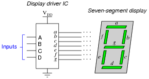
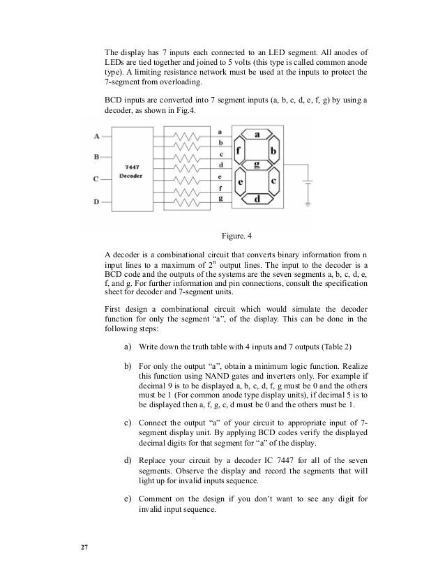
Pin out and image of a seven segment display is shown in the figure below. LED seven segment display system The decoder block converts the given input signal into an 8 line code corresponding to the ‘a’ to ‘g’ segments and the decimal point which controls the segments to display the desired number. For example if the line corresponding to ‘f ‘and ‘e’ are activated then segments f and e of the display glows indicating a “1”. If the input quantity is an analogue signal then it must be converter into digital format using an ADC before applying to the decoder. If the input signal is digital then there is no need for the ADC and the decoder alone will convert the particular input code into the 8 line code compatible to the seven segment LED display. The purpose of the driver stage is to provide the necessary current drive in order to drive the LED seven segment display.
If the decoder stage is powerful enough to drive the display, then the driver stage is not required. A typical 7 segment display driver stage consists of an array (8 nos ) transistor or FET based switches. For example consider the line ‘a’. The “a” output of the decoder is connected to the input terminal (base/gate) of the corresponding switching element inside the driver stage. The same line is buffered by the switching element and is available as output line ‘a’ of the driver. This output is connected to the corresponding ‘a’ element of the display.
The driver can be arranged in sinking or sourcing mode. Sinking and sourcing digital outputs. A sinking digital output keeps the particular output low by using a transistor and thus makes a path for the load current to flow to the ground.
Here the current flows from the load to the respective output terminal. In sourcing mode the the particular output is held high using a transistor the output line itself provides the necessary current for energizing the load. Here the current flows from the output terminal to the load.
The figure shown below illustrates it. Sinking digital output & sourcing digital output In case of the sinking digital output the current comes from the external power supply V+, passes through the load, and the internal transistor conducts it to the ground. For a sourcing digital output the current comes from the digital circuits own power supply V+, then conducted by the transistor, passes through the load and then to the external ground. Seven segment decoder / driver. Seven segment decoder / driver is a digital circuit that can decode a digital input to the seven segment format and simultaneously drive a 7 segment LED display using the decoded information. What that will be displayed on the 7 segment display is the numerical equivalent of the input data. For example a BCD to seven segment decoder driver can decode a 4 line BCD ( binary coded decimal) to 8 line seven segment format and can drive the display using this information.
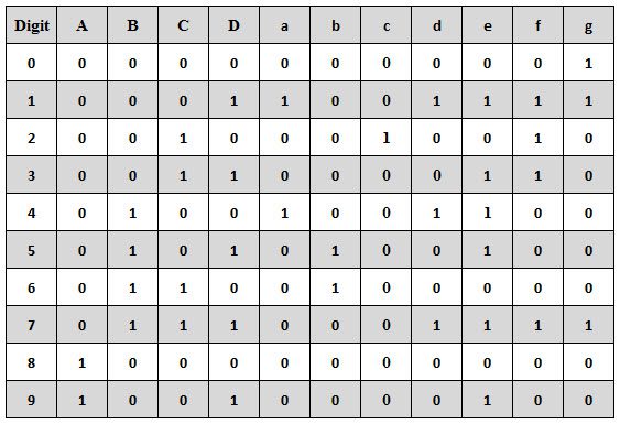
For example, if the input BCD code is 0001, the display output will be 1, for 0010 the display output will be 2 and so on. The circuit diagram shown below is of a BCD to seven segment decoder / driver using 7446 IC. 7446 seven segment decoder driver 7446 is a BCD to 7 segment display driver IC with active low outputs. The IC is stand alone and requires no external components other than the LED current limiting resistors. All output of the IC have complete ripple blanking and requires no external driver transistors. There is also a built in lamp test function which can be used to test the LED segments. Pin 5 of the IC is the ripple blanking input (RBI) and pin 4 is the ripple blanking output (RBO).
Pin 3 is the lamp test (LT) input pin. When the RBI and RBO pins are held high and the lamp test (LT) input pin 3 is held low all LED segment output goes high. The display used here must be a common anode type because the IC has active low outputs.
Quick Links. Characterization of 7-segment display and implementation in Multisim. Specification and test of BCD to 7-segment decoder. exploring pulse-width modulation to control display intensity. Build and test a BCD decoder and 7-segment display with brightness control. This lab is a group activity.
The current group assignments are given. One lab report per group needs to be turned in on D2L. The responsibilites for the successful completion of the lab consist of three parts: The prelab, the actual lab measurements, and the writing of the report. The report will be graded according to three criteria: Correctness, completion, and clarity. On the cover page you must clearly state the student ID (SID) of the group member who had the main responsibility for the prelab, the SID of the group member who had the main responsibility for the lab measurements, and the SID of the group member who had the main responsibility for the report writing.
Design Of Seven Segment Display Driver For Bcd Codes Experiment 2017
Do not put your names on the report, only the student IDs so that there is some degree of anonymity for peer grading. Note that all group members need to be knowledgeable about all three parts, but each member has a specific role in the group. The responsibilities must be rotated for different labs so that each group member experiences all three roles.
An important component of the interface between humans and digital systems is the display of numeric (and alpha-numeric) information. A popular and relatively cheap numeric display device is the 7-segment display. That uses three horizontal and four vertical bars to form the decimal digits from 0 to 9. Since numbers are stored in the form of strings of bits in digital systems, a decoder is needed to convert binary numbers to readable 7-segment patterns. The decoder may incorporate additional features such as blanking of leading zeros, lamp test, and a provision for brightness control. Properties of the 7-Segment Display. The decoder circuit that we will use is designed to drive common anode 7-segment displays.
Design Of Seven Segment Display Driver For Bcd Codes Experiment 1
The means that all positive ends (anodes) of the LED diodes are connected together to the positive end of a power supply and the negative ends (cathodes) of the LEDs are selectively pulled down to ground (through a resistor to limit the current) to light up the corresponding segment. Check the data sheet for the to check the labeling of the segments, the pin assignment for each segment and the maximum continuous forward current per segment. Can you spot the error in the data sheet? In Multisim we will use the following component for animated simulations (i.e., simulations where the segments actually turn on and off depending on the signals applied to the component pins).
Thus, we have to create our own 7-segment display component as explained in. Unfortunately, National Instruments does not allow the creation of animated custom components so the 7-segment display component that you generate will have the correct footprint and will simulate correctly, but it will not show which segments are on or off depending on the applied signals. However, if you create the custom component according to the instructions in then you can change between the animated version and the version with the correct footprint using the 'Replace Components.'
Determine the forward voltage across and the current through the LED for segment A for resistor (R1) values of 100, 120, 150, 180, 220, 270, and 330 ohms. For which resistor value is the current closest to 20 mA? Are all of these resistors safe to use (with a 5 V power supply) or is the current for some of these exceeding the maximum rating of the LDS-A414RI? If so, which? Characterization of the BCD to 7-Segment Decoder.
Look at the datasheet to find out what exactly the 74LS47 BCD to 7-segment decoder is supposed to do. There is a truth table on page 3 of the datasheet that specifies the operation of the decoder. Note that there are 4 binary data inputs (A,B,C,D) and three control inputs (LT',RBI' and BI'/RBO'). To test the 74LS47, build the following schematic in Multisim. Note that this schematic uses the animated 7-segment display part.
Start testing with leaving switches F,G, and H open initially. Check that you can obtain the numbers 0.9 by operating the A,B,C,D switches (switch E controls the decimal point of the 7-segment display directly without going through the 74LS47 decoder). Then check the function of the F,G, and H switches and compare the results to the truth table in the datasheet.

You should find that the 74LS47 model provided in Multisim does not operate correctly. Describe which feature(s) is/are not operating correctly. Download this Multisim schematic and open it in Multisim. Save the 74LS471 component, which implements the correct function of the 74LS47, to the User Database.

Then replace the original 74LS47 in the schematic above by the new 74LS471 as shown below. Observe and characterize the waveforms at the output (pin 3) of the 555 timer circuit and at the upper end of the capacitor (C1) as you change the potentiometer (R2) from about 5% to about 95%. Measure the frequency of the waveform and the average voltage at pin 3 of the 555 timer for several different settings of the potentiometer. If pin 3 of the 555 timer is connected to the BI' input (pin 4) of the 74LS47 in the circuit in problem P2, what do you expect to happen to the 7-segment display? Properties of the 7-Segment Display.

On your breadboard, test the different segments of the 7-segment display using a 5 V power supply and a resistor to limit the current. Check how much current flows through a segment if you use 120, 150, or 180 ohm resistors and compare to the results you obtained in problem P1. Characterization of the BCD to 7-Segment Decoder. Build the circuit shown in the following schematic.